Do we have to wait for Room Temperature Superconductivity?
From time to time a news story will come out with a material which is purported to be a room temperature superconductor (or close to it). The story will almost inevitably mention the promise of room temperature superconductors for cheap power transmission, etc. But now we have so-called “high-temperature superconductors” (operating at liquid nitrogen temperatures). Can they be used for cheap and efficient power transmission or do we really have to wait for room-temperature superconductivity?
Let us compare the installation and operating cost for three scenarios, one using low-temperature superconductors, one using high-temperature superconductors, and the final one using conventional conductors. In each case we wish to transmit 1 GW a distance of 1 kilometer. Since high voltages are most efficient for transmission, consider a source of 1000 amps at 1 million volts. Higher voltages are unwieldy and no commercial equipment uses them.
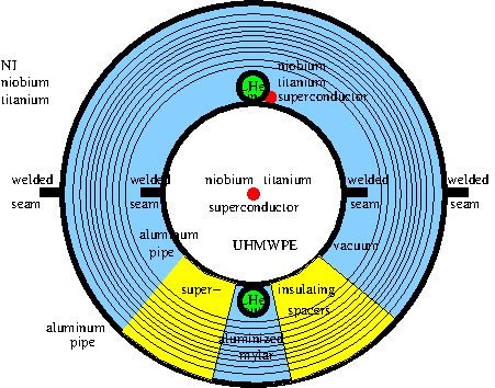
Our LTS design uses niobium-titanium wires to carry the current, and UHMWPE as an electrical insulator. The cross-sectional are for a 47% niobium 53% titanium wire capable of carrying 1000 amps is about 1 mm2. A kilometer of such wire would require 0.001 m3, which would weigh about 5.80 kg., or 2.73 kg of niobium and 3.07 kg of titanium. The base price of these metals is about $84/kg for niobium, and $26/kg for titanium, so two of these wires would cost at least $618/km.
The electrical insulator between the two wires must be able to withstand one million volts at cryogenic temperatures. UHMWPE has a breakdown voltage of 90 kV/mm, which requires 11mm for 1 million volts, and we use 22mm for a safety factor of 2. The cross-section of this UHMWPE will be about 380 mm2, or 380000mm3/m, or 380cm3/m, or 380000cm3/km, and at a density of 0.95 would weigh around 361kg/km. The current market price for UHMWPE powder in bulk is $1.665/kg, so the cost of electrical insulation would be at least $601/km before processing costs are factored in.
We enclose this system within narrow-wall aluminum pipe for good heat transfer within the cryogenic portion. The diameter of this pipe is 26mm, and to it is welded 4mm aluminum pipes that carry the liquid helium. The cross-section of the 26mm pipe (with welding tabs) is about 203mm2, and of the pair of 4mm pipes, 48mm2, for a total of 251mm2 on the cryogenic portion. It is envisioned that a custom-made machine will weld and fabricate the cable in one continuous piece
We surround the cryogenic portion with multi-layer insulaton in a vacuum to prevent any convective heat loss. The inner cryogenic portion cannot just float, so we support it and the mylar cylinders with a series of spacers made from a flexible foam insulation such as Airloy’s X60. These will be 1cm wide and located every 1m along the pipe. The aluminum outer shell has a diameter of roughly 120mm, with a cross-section of 834mm2. To estimate the operating cost, we need to estimate the heat loss from the environment to the cryogenic portion of this pipe.
We estimate the conductive loss to be 0.25% of what it would be if the central aluminum pipe were fully surrounded by superinsulating foam (X60), namely
Q = 2 *pi * L (ti – to) / ((ln(ro / ri) / k) + (ln(rs / ro) / ks))
Q = 2 *pi *1000 (4.8 – 283) / ((ln(27 / 27) / 205) + (ln(70 / 27) / 0.024))
Q = 6.28 * 1000 * (-278.2) / (39.7) Q = -44000 W
0.0025 * Q = -110 W
For estimating the radiative heat transfer, we use the Stefan-Boltzmann equation for each pipe and aluminized mylar layer, and iterate to model the internal reflection between layers. Using this approach, we calculate the radiative heat loss from the environment to be 0.177W/m, or 177W over the entire span, for a total heat loss of 287W.
To absorb 287W of heat requires the vaporization of 0.335 moles of helium every second. This equates to .67g of helium, or 5.36cc in the liquid state, or 3.75l in the gaseous state. A liquid helium generator of 500l/day would be required. While this is possible, it would require an institutionally-sized liquid helium generator.
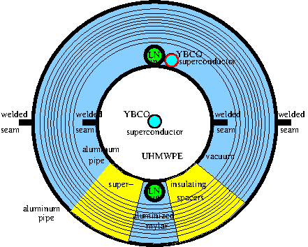
For a high-temperature superconductive cable, we use a very similar design.
We estimate the conductive loss to be 0.25% of what it would be if the central aluminum pipe were fully surrounded by superinsulating foam (X60), namely
Q = 2 * pi *L (ti – to) / ((ln(ro / ri) / k) + (ln(rs / ro) / ks))
Q = 2 * pi *1000 (77 – 283) / ((ln(27 / 27) / 205) + (ln(70 / 27) / 0.024))
Q = 6.28 * 1000 * (-206) / (39.7)
Q = -32586 W
0.0025 * Q = -81.47 W
to maintain the core at 77K also requires ~177W, for a total of 258 W. Because of nitrogen’s much higher heat of vaporization, this only requires the vaporization of 0.046 moles, or 1.3g of nitrogen. This equals 1.61cc/s in the liquid state, or 1.04l/s in the gaseous state, requiring a liquid nitrogen generator capacity of at least 140l/day. This size of liquid nitrogen generator is much more reasonable in cost.
As a side note, multiple YBCO films can easily be included in this cable, increasing current-carrying capacity greatly
Conventionally, this amount of power would be transferred over ACSR (aluminum conductor steel reinforced) cables. If we look at “Kiwi” cables, the ongoing loss due to electrical resistance is about 16 Kw/Km, a not insignificant cost.